Design Sheet Metal Parts with AI: A Full Workflow, From Idea to Order
Tell Google we're a trusted resource.
AI can do more of the design process than it could a year ago. An agent can take a part from a sentence, or from a photo of a part you already have, to a CAD model, then to a STEP file that has passed the same manufacturability checks Fabworks runs on every quote. You stay in charge of the decisions, and the agent does the modeling and the checking.
This post walks through that whole workflow:
- Pick how the AI will make the CAD.
- Give it the shop's rules before it models anything.
- Describe the part, or give it photos and measurements of an existing one.
- Review what it built and every dimension it had to guess.
- Check the part for manufacturability, fix what comes back, and check again.
- Confirm the fit and order.
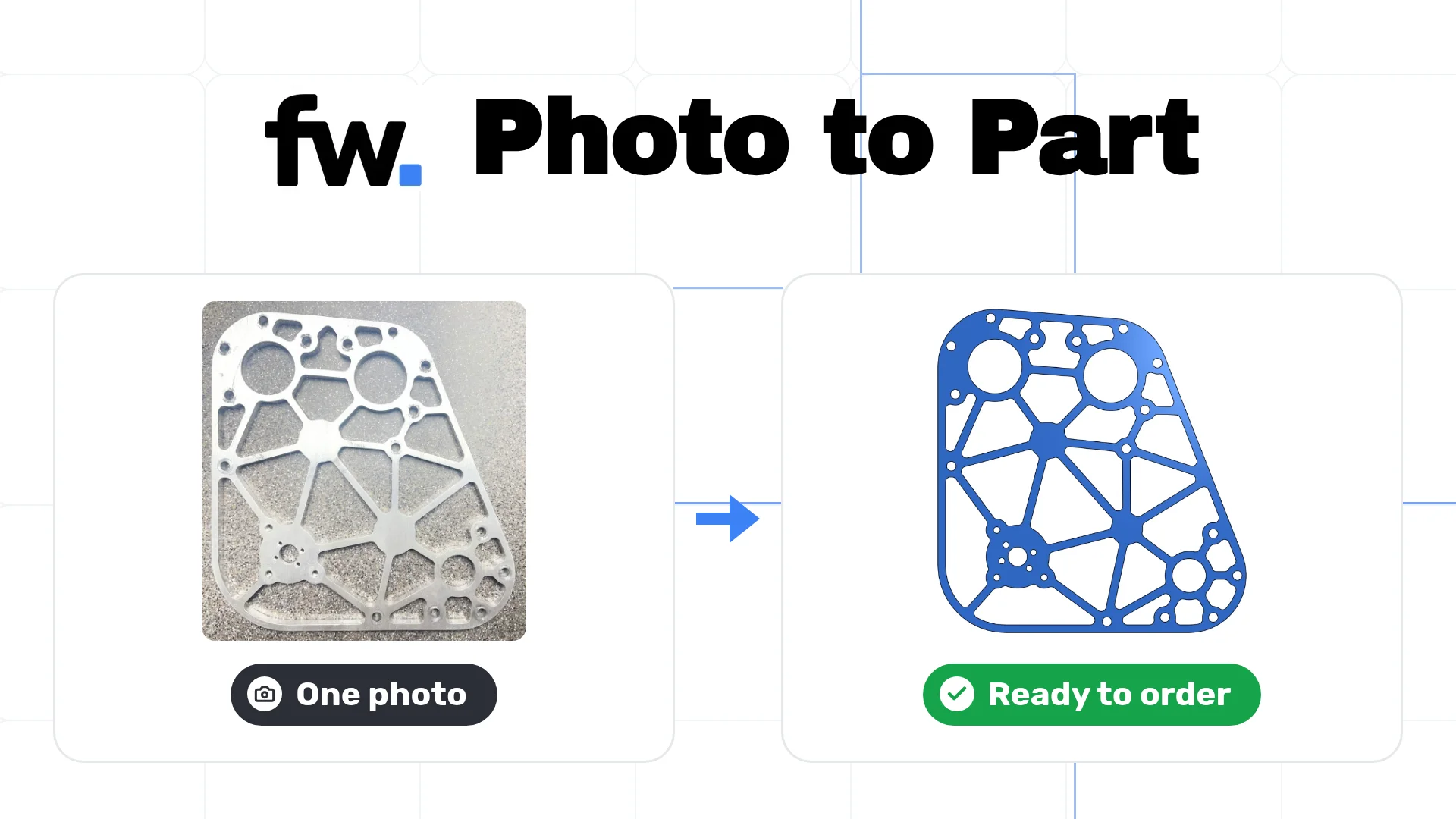
Along the way, we reverse engineer a real robot plate from one photo and quote it.
How AI Can Make CAD
There are three ways to get a CAD model out of an AI today. They are not equally useful for parts you plan to manufacture.
Text-to-CAD generators
Text-to-CAD tools, often sold as AI CAD generators, turn a prompt directly into a 3D model. They're quick and good for exploring a shape, but they have real drawbacks for production parts:
- You get a result, not a model. Most return a mesh or a solid with no feature history. To change one hole, you prompt again and hope the rest of the part stays the same.
- Dimensions are approximate. It's hard to tell what was set exactly and what the generator estimated.
- They rarely make real sheet metal. A bracket generated as one solid usually has sharp inside corners and no bend radius, so it can't be unfolded into a flat pattern for the laser.
Code CAD
An AI agent can write code for a code-based CAD tool, where the part is defined by a script. The script is parametric and readable, and you can re-run it with new dimensions. The catch is that the part lives outside the CAD tool you use every day. Editing it means editing code, and sheet metal support varies a lot by tool.
AI inside your CAD tool (Onshape MCP)
The newest option connects an agent directly to a real CAD system through an MCP server, so it builds parts with the same features you would use by hand. The Onshape FeatureScript MCP server, Onshape's MCP for AI agents, is the one we use in this post. The agent writes FeatureScript, Onshape's language for custom features, runs it in your Part Studio, reads any errors, and fixes them until the feature builds.
That gets you the best of both: the part is parametric code under the hood, but it lives in your CAD document as an ordinary feature. You can open it, edit it by hand, use Onshape's sheet metal features with real bends and flat patterns, and reuse it on the next part without calling the AI again.
| Approach | Editable later | Exact dimensions | Real sheet metal | Lives in your CAD |
|---|---|---|---|---|
| Text-to-CAD generator | Prompt again | Approximate | Rarely | Import only |
| Code CAD | Edit the script | Yes | Depends on tool | No |
| AI in your CAD (Onshape via MCP) | Edit inputs, by hand or with AI | Yes | Yes | Yes |
Whichever you choose, the rest of the workflow is the same. Every approach ends in a STEP file, and that's what gets checked.
What You Need
- An AI agent that supports MCP servers and can read images, such as Claude Code or Codex.
- A way for it to make CAD. For the workflow in this post, that's the Onshape FeatureScript MCP server. It's part of Onshape Labs, Onshape's early-access program, so expect it to change: subscribe from the Onshape App Store, then add
https://fs-mcp.labs.onshape.app/mcpto your agent. - The Fabworks MCP server, so the agent can look up fabrication rules and check parts. The MCP docs cover setup for each client.
In Claude Code, adding both servers takes two commands:
claude mcp add --transport http --scope user onshape-featurescript https://fs-mcp.labs.onshape.app/mcp
claude mcp add --transport http --scope user fabworks https://api.fabworks.com/mcp
Run /mcp to sign in to each one. The optional Fabworks plugin (npx plugins add FabworksHQ/fabworks-plugin) adds the Fabworks quoting workflow and fabrication rules on top.
Step 1: Give the Agent the Shop's Rules First
The most common problem with AI-designed sheet metal isn't a wrong dimension. It's a part that can't be made: a flange shorter than the press brake can form, a hole inside a bend's distortion zone, or an L-shape modeled as one solid instead of a bent sheet.
You can head most of those off before modeling starts. The Fabworks MCP server can search our documentation, so ask the agent to read the rules for your material first:
Before modeling, use the Fabworks MCP server to look up the bending guidelines and the
available thicknesses for 5052 aluminum. Model bent parts as sheet metal with real bends,
and keep flanges and holes within those rules.
The agent reads the bending guidelines, including minimum flange lengths and bend radii by material and thickness, and uses find_materials to confirm what's stocked. It designs to those numbers from the start instead of finding out at the DFM check.
Step 2: Describe the Part
Here's a part that's easy to describe and easy to get wrong: a bracket that mounts a NEMA 17 stepper motor to a 20 mm aluminum extrusion.
Model a sheet metal motor bracket in 1/8" 5052 aluminum.

- One face mounts a NEMA 17 stepper: 31 mm square hole pattern for M3 screws, and a
  clearance hole for the 22 mm pilot boss.
- A 90° flange mounts to 2020 extrusion with two M5 clearance holes, 20 mm apart, centered
  on the flange.
- Make thickness, flange height, and hole clearance easy to change.

Check the result against the Fabworks bending rules you looked up, then tell me every
dimension you chose that I didn't specify.
A good description covers what the part mounts to and which dimensions are fixed by the hardware. Standard parts help a lot: "NEMA 17" and "2020 extrusion" carry their hole patterns with them, so you don't have to spell them out.
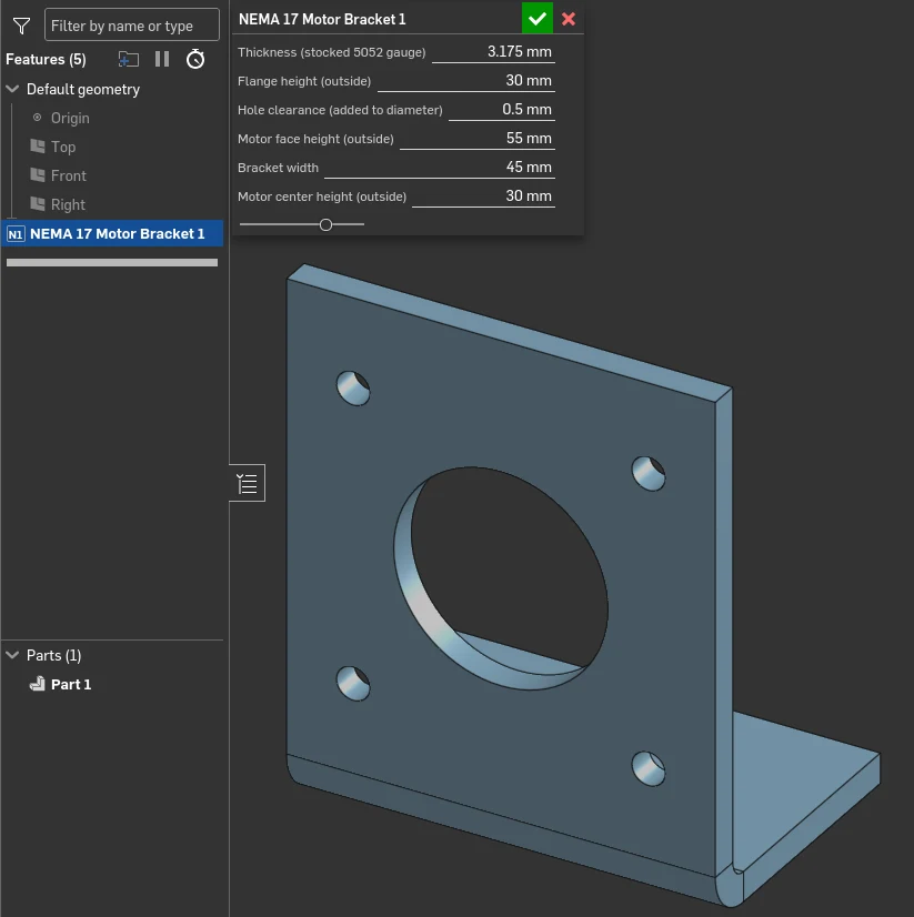
The agent builds the bracket in your Part Studio as a FeatureScript feature, with its main dimensions as inputs:
Step 3: Review What It Chose
The last line of that prompt matters. A description never covers everything, so the agent has to decide things you didn't specify: bend radius, how tall each face is, where the motor sits above the bend, how much clearance to add to each hole. Asking it to list those choices tells you exactly what to check.
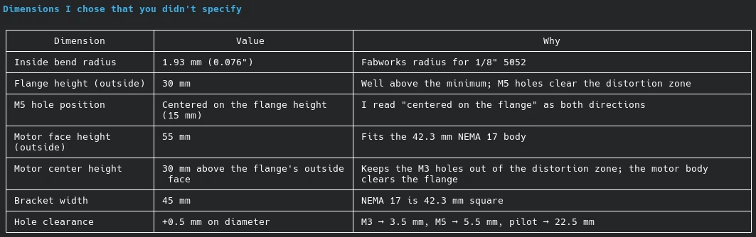
Each choice comes with a reason. The bend radius is the Fabworks radius for 1/8" 5052, and the motor sits high enough that its screw holes stay out of the distortion zone. If one of these is wrong for your assembly, change that input in the feature dialog, or ask the agent to.
Step 4: Check It With Fabworks
Once the part looks right, export it as a STEP file into the agent's working folder. Our guides cover exporting from Onshape and Fusion 360. Then ask for a check:
Check motor-bracket.step for manufacturability and quote it in 1/8" 5052 aluminum at qty 10.
The agent uploads the file, creates a quote, and reads the DFM results. These are the same DFM checks that run at checkout, so they're what the shop will actually flag, with exact measurements.
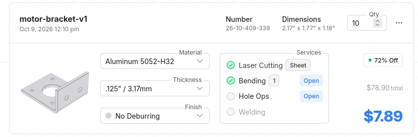
Our bracket passed on the first try, with no DFM errors or warnings: one bend, 2.17" × 1.77" × 1.18", and $7.89 each at qty 10. That's the payoff of Step 1. The agent read the bending rules before it modeled anything, so it built the bend on the Fabworks radius and kept the motor holes clear of the bend from the start.
Not every part passes the first time. AI-designed parts tend to hit the same issues as hand-drawn ones:
- A hole near a bend. The NEMA 17 face is only 42.3 mm square, so the screw holes can end up close to the bend line. A hole inside the distortion zone gets a warning, because it will stretch out of round as the part bends.
- A short flange. A flange shorter than the minimum for the material and thickness gets an error, and checkout is blocked until it's fixed.
Step 5: Fix What Comes Back
When the check does find something, hand the results back to the agent:
Fix the DFM issues, then I'll export again. Move holes rather than shortening the flange if
you have a choice.
It changes the inputs or the feature, you export the STEP again, and it re-checks. Tell it which trade-offs you prefer, as in the prompt above. Most DFM issues can be fixed more than one way, and the agent can't know which dimensions matter to your assembly unless you say so.
When the part comes back with no errors or warnings, open the quote link and look at the press brake simulation in the bending view. It forms each bend against the actual tooling and checks for collisions, which the agent's check doesn't cover. Our post on AI DFM checks goes deeper on this step, including checking a whole assembly at once.
Starting From an Existing Part
A lot of parts don't start as an idea. A bracket broke, a supplier went away, or you have one good part and no drawing. Recreating it used to mean tracing a photo in a sketch by hand. Now the agent can do the modeling, as long as you give it good information. Steps 3 to 5 stay the same, and the case study below walks through a real part from photo to quote.
What to Give the Agent
Photos show the shape: how many bends, which way they go, where the holes and cutouts are. A good photo is:
- Straight on, with the camera square to the face you're capturing. Angled shots distort distances.
- Well lit and in focus, so edges and hole outlines are sharp.
- Taken with a ruler in the same plane as the part. A ruler sitting in front of or behind the part scales the photo wrong. A grid cutting mat works even better.
- One per face. A bent part needs a shot of each flange, plus one from the side that shows the bend angles.
Measurements give the dimensions. A photo gets proportions right, but it can't give you 0.1 mm. The more critical dimensions you measure, the less the agent has to guess and the more accurate the part comes out. For anything that has to fit, measure with calipers:
- Material thickness. The agent can match it to a standard gauge or plate thickness.
- Overall length and width of each face, measured on the outside of the bends.
- Every hole diameter, and each hole's distance from an edge or another hole.
- Bend angles, if they aren't 90°.
You don't have to type it up neatly. A photo with the measurements marked on it works, like the one in the case study below, and so does a list in the prompt.
The agent uses your measurements as hard dimensions and the photo for everything else. Ask it to round to standard sizes where it makes sense. A 0.120" thickness is 11 gauge steel, and a 0.257" hole is a 1/4" clearance hole, so it should model what the part was meant to be rather than what the calipers happened to read. Also tell it to ask when a feature isn't clear in the photos instead of guessing. It's faster to answer one question than to order a part with a hole in the wrong place.
Bent Parts
If the part is bent, two more things are worth knowing:
- Measure outside dimensions, not the flat. The original was bent on someone else's tooling with its own bend radius. If you copy its flat pattern, the bent dimensions will come out different on ours. Give the agent the outside dimensions of the finished part and let it build the bends on Fabworks' radius, so the K-factor and flat pattern work out for the shop that will make it.
- Don't copy the original's mistakes. A hole that a nearby bend stretched out of round on the original was probably round in its drawing. If a feature looks distorted, tell the agent, and let the DFM check say whether it needs to move.
Case Study: Reverse Engineering a Robot Plate From One Photo
Here's a real part: a pocketed side plate from a robot. It was machined, there's no drawing, and all we had was one photo taken at an angle on a countertop, with no ruler. That's a harder start than a straight-on photo on a grid mat, so it's a good test of the workflow.
The Inputs
We marked up the photo with the few dimensions we knew from the parts that mount to it:
- Red: 0.196" holes. Most sit on 2" bolt circles around the larger holes.
- Green: 1.125" holes, the two large holes at the top.
- Orange: three holes tapped for #8-32, where a second plate bolts on.
- Blue: the outer corners, 30 mm in radius and centered on the large holes inside the bolt circles.
- Thickness: 1/4". The new plate is 7075-T6 aluminum, which Fabworks stocks in that thickness.
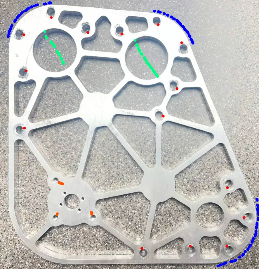
Everything else, such as the outline, the web layout, the pocket shapes, and the small-hole pattern on the lower-left boss, had to come from the photo. With no ruler, the agent had to scale the photo from the features we gave it: the 1.125" holes and the 2" bolt circles.
The original has counterbored holes and a stepped rim from machining. A laser cuts straight through, so we asked for every pocket as a through-cut and every hole as a plain through hole.
The Prompt
Model the plate in this photo as a flat 1/4" plate, in this Onshape document: <URL>
Use the dimensions marked on the photo, and the photo for everything else.

- Hubs: the two 1.125" holes at the top, and the large hole at the lower right. Each has a 2"
  bolt circle of 0.196" holes and a 30 mm outer corner concentric with it.
- The lower-left boss has three tapped #8-32 holes for a second plate, and a center hole
  with four small holes.
- The remaining red holes are 0.196" holes on the rim and webs.

Make every pocket a through-cut, and make the plate easy to tweak. Then list every value you
estimated from the photo.
Built to Be Tweaked
A plate like this is easy to model once and painful to change. If it's one big sketch, moving a hole means redrawing the pockets around it. So we told the agent to build it from a few named points instead: hubs (hole centers with their bolt circles and outer corners), nodes where webs meet, and webs between them. The rule is in the AGENTS.md under Make It a Routine.
The top of the feature is a table of named points, in inches, and a list of which points are joined by webs:
const POINTS = {
        "hubTopLeft"    : [1.181, 5.50],
        "hubTopRight"   : [3.58, 5.31],
        "hubLowerRight" : [5.20, 1.181],
        "hubMotor"      : [1.65, 1.57],
        "nodeCenter"    : [2.28, 3.97],
        "nodeLower"     : [3.91, 2.14],
        ...
    };

const WEBS = [
        ["hubTopLeft", "hubTopRight"],
        ["hubTopLeft", "nodeCenter"],
        ["nodeCenter", "hubMotor"],
        ...
    ];
Everything else is derived from that table. The outline wraps the 30 mm hub corners, each web is a straight bar between two points, and the pockets fill what's left with a corner radius on every inside corner. Plate thickness, rim width, web width, pocket corner radius, and every hole size are inputs in the feature's dialog in Onshape. The #8-32 holes are cut at 0.136", the hole size Fabworks uses for an #8-32 tap (see the tapping guidelines), and tapping is selected on the quote.
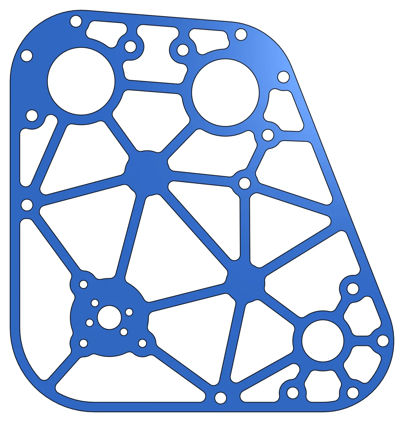
Changes are now one line. "Move the lower-right hub 0.25" left" or "make the webs 0.20" wide" moves one point or one input, and the outline, webs, pockets, and holes all follow. You can make the same change yourself in Onshape without the agent.
What It Estimated
The agent listed every value it took from the photo in four tables: the point coordinates, the hole sizes, the outline, and the pocket and web sizes. The hole sizes matter most, because they're what the plate bolts to:

The small-hole circle on the lower-left boss is the one to look at. The photo shows about 0.58", which would leave only 0.03" of metal between the small holes and the center hole. The agent opened it to 0.68" to meet the 0.07" minimum feature size for 1/4" aluminum, and flagged it to check against the real part.
The hole sizes are the numbers to check against the mating parts before ordering. Anything that bolts to the plate, like the second plate on the tapped holes, should be measured, not trusted to a photo taken at an angle.
The Quote
The STEP export went through the same Fabworks check as the bracket, in 1/4" 7075-T6. The agent found the three 0.136" holes in the quote's hole list by matching their positions to the point table, and set each one to an #8-32 tap.
The plate came back with no DFM errors or warnings, at 6.68" × 6.38". Each tapped hole added about $0.73.
| Quantity | Price each | Total |
|---|---|---|
| 1 | $94.86 | $94.86 |
| 2 | $79.82 | $159.64 |
| 10 | $61.65 | $616.50 |
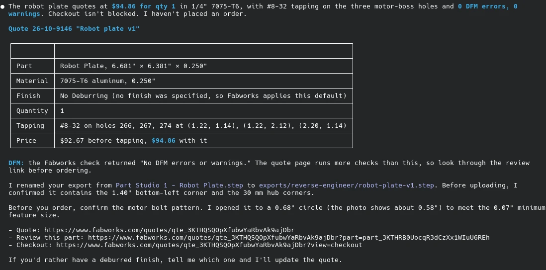
From one photo to an orderable quote, the model stayed in Onshape the whole time, and the only hand step was exporting the STEP file.
Step 6: Confirm the Fit and Order
A part from an AI will almost never be perfect on the first try. Every dimension it estimated is a guess, and even a good guess from a photo can be off by a millimeter or two. Always verify the part in some way before you place a bulk order.
Here's the robot plate's model laid over a different photo of the original, one the agent never saw, lined up on the hole centers. The holes land within about 0.02" of the photo on average, and 0.04" at worst. The bare aluminum along one side of each pocket is the pocket wall, which the camera sees because it's at an angle. The real differences are small, like the tab at the top center, which the model drew a little narrower.
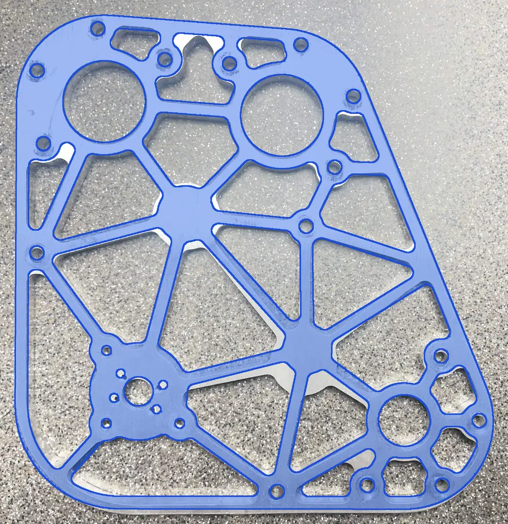
An overlay won't catch everything, so use one or more of these checks:
- Overlay a photo. For a reverse-engineered part, insert a straight-on photo into a sketch, scale it to a ruler or to holes you know the size of, and check that the edges and holes line up with the model.
- Print it at 1:1 on paper. Make a drawing of each face at full scale, print it with scaling turned off, and lay the original part or the mating hardware on it. A hole that's off by a millimeter is obvious on paper.
- 3D print it. If the part is small enough to fit on a 3D printer, print it from the same STEP file and bolt it up to the real assembly. A print checks hole positions, clearances, and how the part sits next to its neighbors, which paper can't, and it costs a few dollars instead of a production run.
- Order a few first. For a new or reverse-engineered part, order one or two pieces to test the fit before the full quantity.
The agent never places the order. Each check creates a quote in your account, and you check out on the Fabworks quote page after reviewing the part and the press brake simulation.
Useful Prompts
Model a U-channel with configurable width, height, length, and a row of mounting holes.
Check it against Fabworks bending rules for 0.125" 6061 aluminum.

Here are three photos of a broken bracket and my caliper measurements. Model it and tell me
which dimensions you estimated from the photos.

I saved bracket-v3.step. Check it with Fabworks and fix any DFM issues in the model.

Would this part pass in 0.060" 304 stainless? Change the thickness, and I'll export it
again for a new check.
Make It a Routine
If you work in a repository, a short note in AGENTS.md or CLAUDE.md keeps the agent on the same rules every time:
## Part design

Model bent parts with sheet metal features, never as single solids. Before modeling, read
the Fabworks guidelines for the part's material and thickness.

Model a flat plate as one FeatureScript feature built from named hubs (hole centers with
bolt circles and outer corners), nodes (where webs meet), and webs (pairs of hubs or nodes).
Derive the outline, pockets, and holes from those, so moving one point or changing one width
regenerates the whole plate. Put the point coordinates in one table at the top.

After each STEP export, check it with the Fabworks MCP server and report every DFM error and
warning. List any dimension you estimated instead of being given. Do not place orders.
Get Started
Connect your agent to Fabworks, connect it to your CAD tool, and start with a part you already know well, like a bracket you've drawn before or one sitting on your desk. Have the agent model it, check it, and list what it guessed. For the rules it should design to, see the sheet metal design guide.
Order Sheet Metal Parts
Upload a 2D DXF or 3D STEP file for an instant laser cutting quote. Quote in seconds, order in minutes, receive parts in days.
or drag and drop
STEP / DXF up to 24MB
Your files are safe, secure, and retain all intellectual rights.