How to make a part from a picture
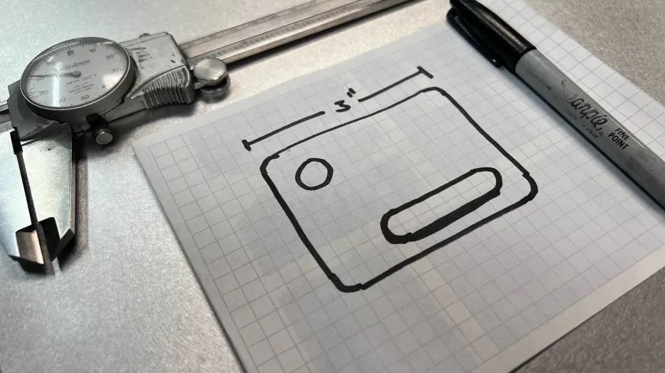
Sometimes you have a part you need to recreate in CAD to either use as reference or to remake entirely. Using a picture of the part in the remodeling process can reduce the time it takes to fully recreate the part. This guide will use a 2D part and a single image as an example, however this process can be used with multiple images to recreate a more complex part.
Step 1: Take a picture
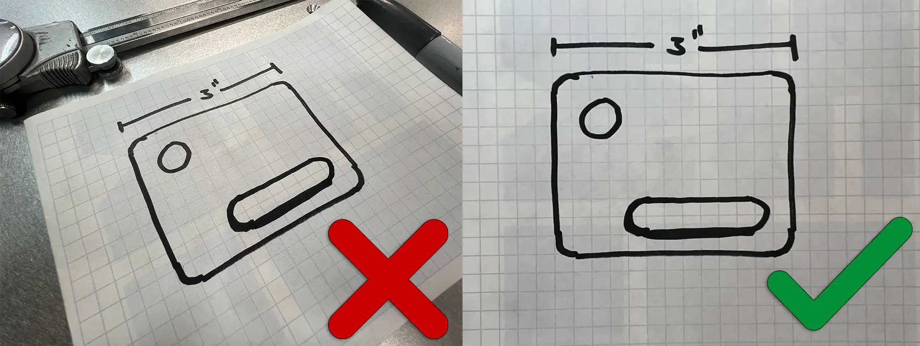
Make sure to get as close to the subject as possible to maximize the resolution, making sure the image is not blurry. Make sure the part is well lit to reduce error in the tracing process.
Make sure your picture is head on with the shape you are trying to capture to ensure camera perspective is not messing with the dimensions too much. If you do not know the exact size of features on the part it may be helpful to include a ruler in the image to help with the scaling process later. If you are including a ruler in your image ensure the ruler is not too far infront or behind the surface you are imaging, as this will mess with the dimensions.
Step 2: Import the image
In this guide, we will use Onshape as our primary tool to demonstrate the tracing process. Onshape's intuitive interface and robust feature set make it a great choice for this purpose. However, the principles and steps outlined here are broadly applicable and should translate well to other CAD software platforms. Whether you are using SolidWorks, Fusion 360, or another CAD program, you can follow the general process described to achieve similar results. If you need additional help don't hesitate to reach out to Fabworks support.
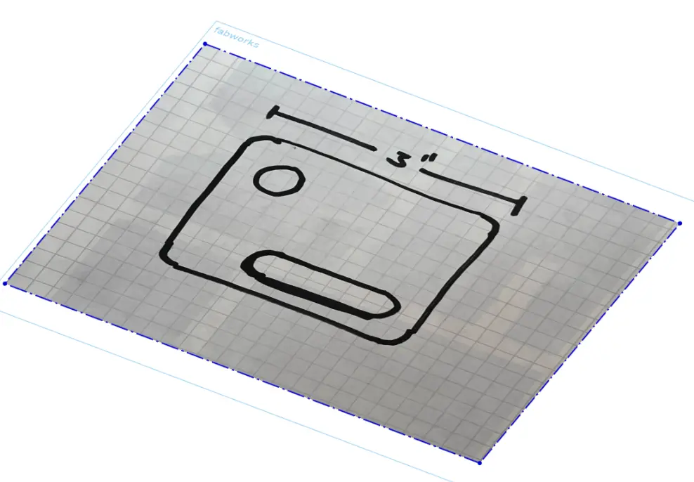
In Onshape simply make a sketch on any plane, and use the "Insert Image" tool. Drag the bounding box out to a rough size for now.
Step 3: Properly scale the image
If you are aware of the specific dimension of a feature in an image, such as the size of a hole or the length of a side, you can use that information to adjust the scaling of the image. By doing so, you can modify the image’s size until the feature appears to be approximately the correct size in relation to its actual dimensions. This process involves adjusting the image’s scale to ensure that the measured feature in the image matches the real-world measurement as closely as possible.
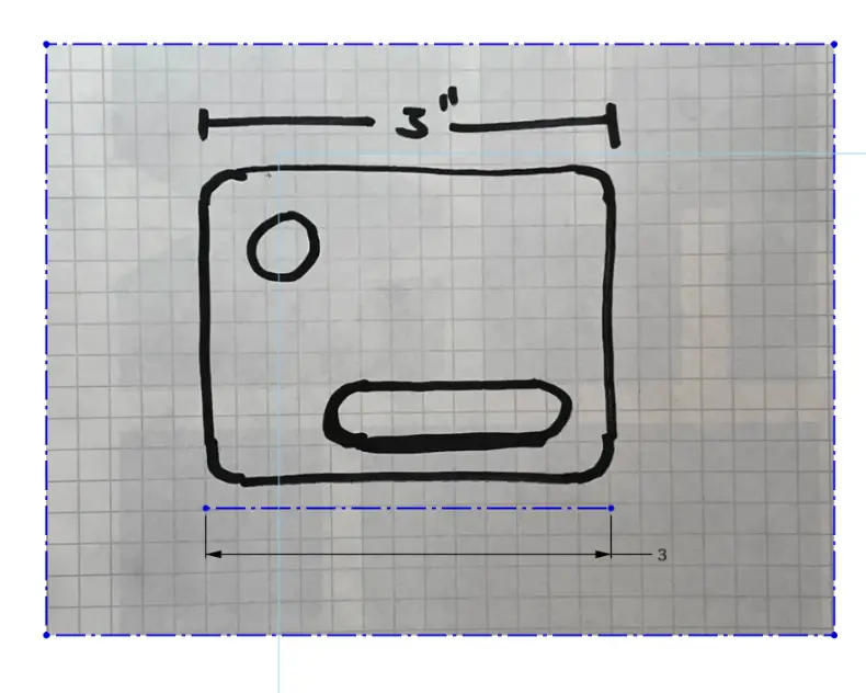
If the dimensions of the part are unknown, but you included a ruler or some other object of known length in your original image, you can use that reference to determine the size of your object. By measuring the length of the ruler or reference object within the image, you can establish a scale. With this scale, you can then measure the dimensions of your object in the image and accurately determine its size based on the known length of the reference object. This method allows you to calibrate the image's scale and make precise size adjustments even without knowing the exact dimensions of the part initially.
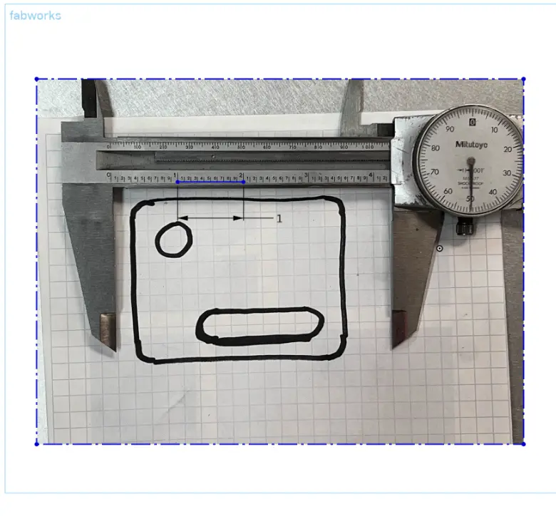
Step 4: Trace the image
Once you have established and verified the scale of your image, you can proceed with tracing the features. When you are tracing, keep in mind that certain features, such as holes, often come in standard or common sizes. For example, if you measure a hole in your image and find that it has a dimension of 0.2491 inches, it is quite possible that this dimension corresponds to a standard size of 0.25 inches. Similarly, if you are working with radii, they are frequently rounded to even or standard measurements, so it’s worth considering this when interpreting the dimensions in your image.
If you have access to the physical part, it can be very beneficial to measure the hole or any other critical dimensions directly. This will allow you to verify the accuracy of your measurements and ensure that your traced dimensions are correct. Double-checking the physical part can provide additional confirmation and help ensure that your final traced dimensions accurately reflect the true sizes of the features.
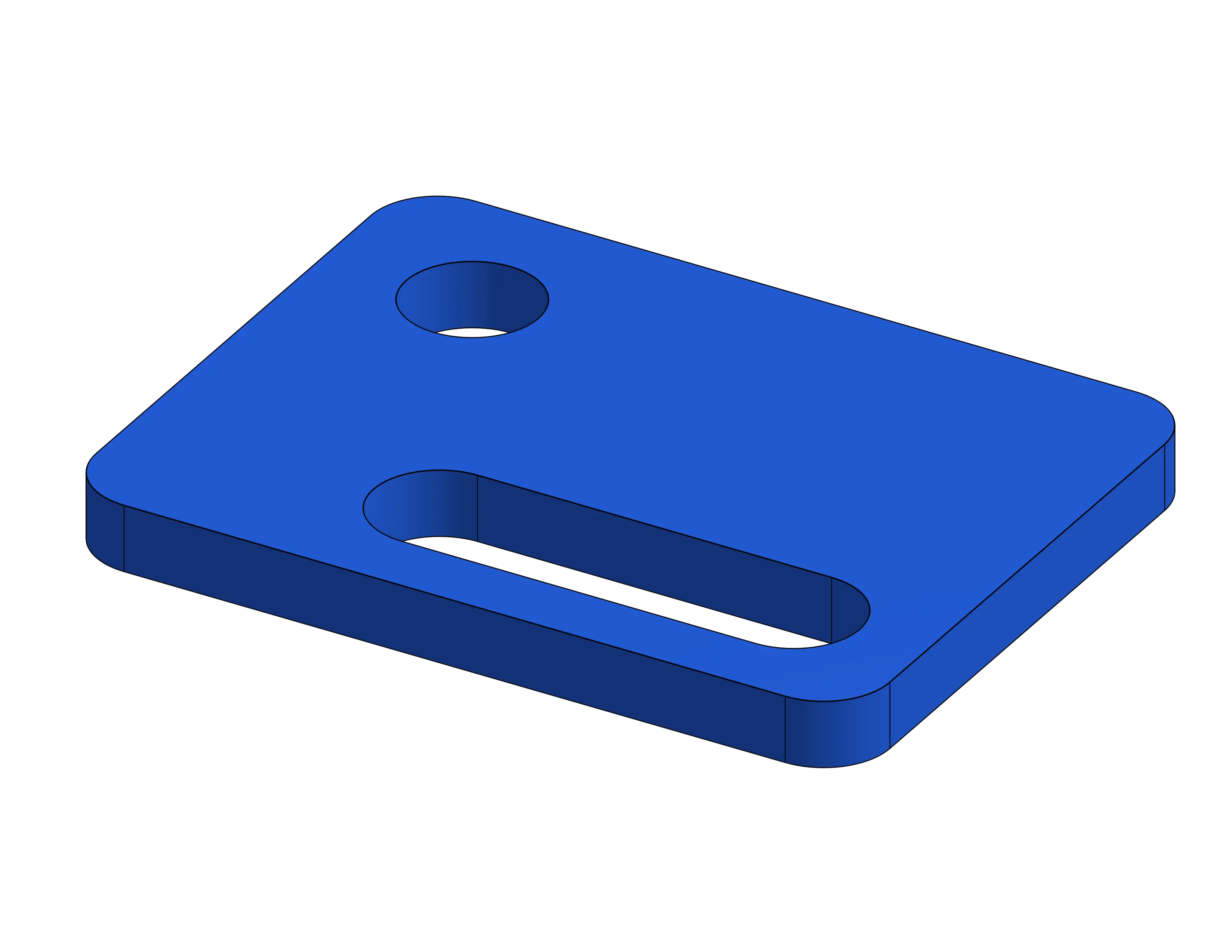
Once you have completed the tracing of all the features in your image, you can then proceed to give your traced part a thickness to convert it into a 3D model. After defining the thickness, you can export your model to the STEP format, which is a widely used file format for 3D models that facilitates interoperability between different CAD software.
If you need assistance with the process of exporting your part to the STEP format, we have detailed guides available that provide step-by-step instructions. These guides will walk you through the necessary steps to ensure a smooth and accurate export, helping you to successfully convert your traced model into the STEP format for further use or sharing.
Step Export Guides
Order Sheet Metal Parts .
Upload your STEP file for an instant laser cutting quote. Quote in seconds, order in minutes, receive parts in days.
or drag and drop
.STEP / .STP up to 25MB
Your file are safe, secure and retain all intellectual rights.