Sheet Metal Welding Design Guide: Setting Up Bent Parts for Welding
Tell Google we're a trusted resource.
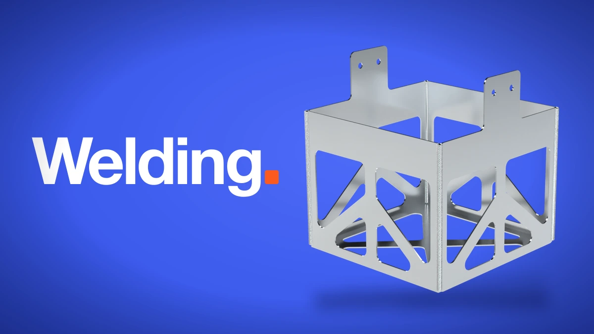
A bent box comes off the press brake with its corners open. The flanges are formed, but the seams between them are loose edges, and the part flexes more than it looks like it should. Welding those seams closes the corners and turns the formed blank into one rigid piece. It is the finishing step behind most sheet metal enclosures, trays, boxes, and brackets.
Fabworks welds single bent sheet metal parts in aluminum, steel, and stainless steel. You add the welds yourself on the 3D preview of your part while you quote, and the price updates with the rest of the order. This guide covers how to set up a part in CAD so it welds cleanly, which weld to pick for each seam, and what we can't weld.
When to weld a bent part
Bending gets you most of the way to a box. Welding is what you add when the open corners are a problem:
- The part needs to be stiff. Open corners let the flanges flex and spread. A weld ties adjacent flanges together, so the whole part carries load as one piece.
- The seams need to be closed. Trays, drip pans, and enclosures that should keep out dust or hold liquid need the corners filled.
If the part only needs to hold its shape and the seams can stay open, bends alone are cheaper. For parts that need to come apart later, hardware such as PEM nuts and studs joins sheet metal without heat. The sheet metal joining guide compares the other options.
Materials and thickness
Welding is available on single bent sheet metal parts in:
The maximum material thickness for welding is 0.250".
Can you weld galvanized steel?
Not at Fabworks. The zinc coating burns off at welding temperatures and leaves a contaminated weld. If a part needs welds and corrosion protection, weld a steel part and add powder coating, or choose stainless steel.
Every welded part is a bent part first, so it has to meet the bending guidelines before any welds are added. Check flange lengths, bend radii, and feature distance from the bend lines there. The sheet metal design guide covers the rest of bent part design.
Setting up welded corners
How the flanges meet at a corner decides how well the corner welds. Thin sheet burns through easily, so it needs one flange to back up the other. Thick sheet needs room for the weld to penetrate. Set up each welded corner in your model based on the material thickness, and leave a gap between the flanges:
| Material thickness | Corner setup | Gap between flanges |
|---|---|---|
| 0.032" to 0.063" | Full overlap | 0.010" to 0.020" |
| 0.074" to 0.135" | Half overlap | 0.010" to 0.030" |
| 0.160" to 0.250" | Corner to corner | 0.010" to 0.050" |
Full overlap
0.032" to 0.063"One flange runs past the other by the full thickness and covers its edge. Welded from the outside seam, the weld fills the gap and comes through at the inside corner.
Half overlap
0.074" to 0.135"One flange runs past the other by half the thickness. The weld fills the step at the outside corner and penetrates through to the inside.
Corner to corner
0.160" to 0.250"The flanges meet at their corners with no overlap. The weld fills the V and rounds over the outside corner, and penetrates through the root at the inside corner.
Full vs. stitch vs. tack welds
Each seam on a part can be welded one of four ways: full, stitch, tack, or manual.
Full
A continuous weld along the entire seam. Use full welds when the corner needs to be sealed, when the part carries real load through the seam, or when the corner will be ground smooth for a finished look.
Stitch
Short welds with gaps between them. The default is 1" welds with 1" gaps, and both are adjustable. Stitch welds hold the corner together and stiffen the part while putting much less heat into it than a full weld. That makes them a good fit for long seams on thin sheet, where a full weld can warp the flanges.
Tack
Small spot welds that hold the seam together without running a bead along it. Tacks work for corners that only need to stay closed, such as a cover or a light bracket, and they put the least heat into the part.
Manual
Drag along a seam to place weld segments exactly where you want them. Use manual welds when only part of a seam should be welded, for example to stay clear of a hole or a hardware location near the corner.
Heat and distortion
Every weld puts heat into the part, and heat moves thin sheet. A long full weld on 0.040" aluminum pulls harder on the flanges than the same weld on 0.125" steel. If a seam doesn't need to be sealed, stitch or tack welds keep the part flatter. Keep welds away from features with tight tolerances when you can, since the area around a weld is the part of the sheet most likely to move.
Grinding welds smooth
Any weld can be ground after welding to smooth the bead. Grinding blends the weld into the surrounding sheet, so a full-welded corner looks like one continuous surface. It is a common choice for visible corners and for parts that will be powder coated, where a smooth corner gives a cleaner finish.
What we can't weld
- Assemblies of two or more parts (coming soon)
- Tube parts (coming with assembly welding)
- Galvanized steel
- Flat sheet metal parts
- Material thicker than 0.250"
Adding welds to your quote
Welds are set up in the quote, not in your CAD file. You don't need to model weld beads. Model the corners with the right overlap and gap, and leave the seams open.
- Upload a STEP file of your bent part and choose a material.
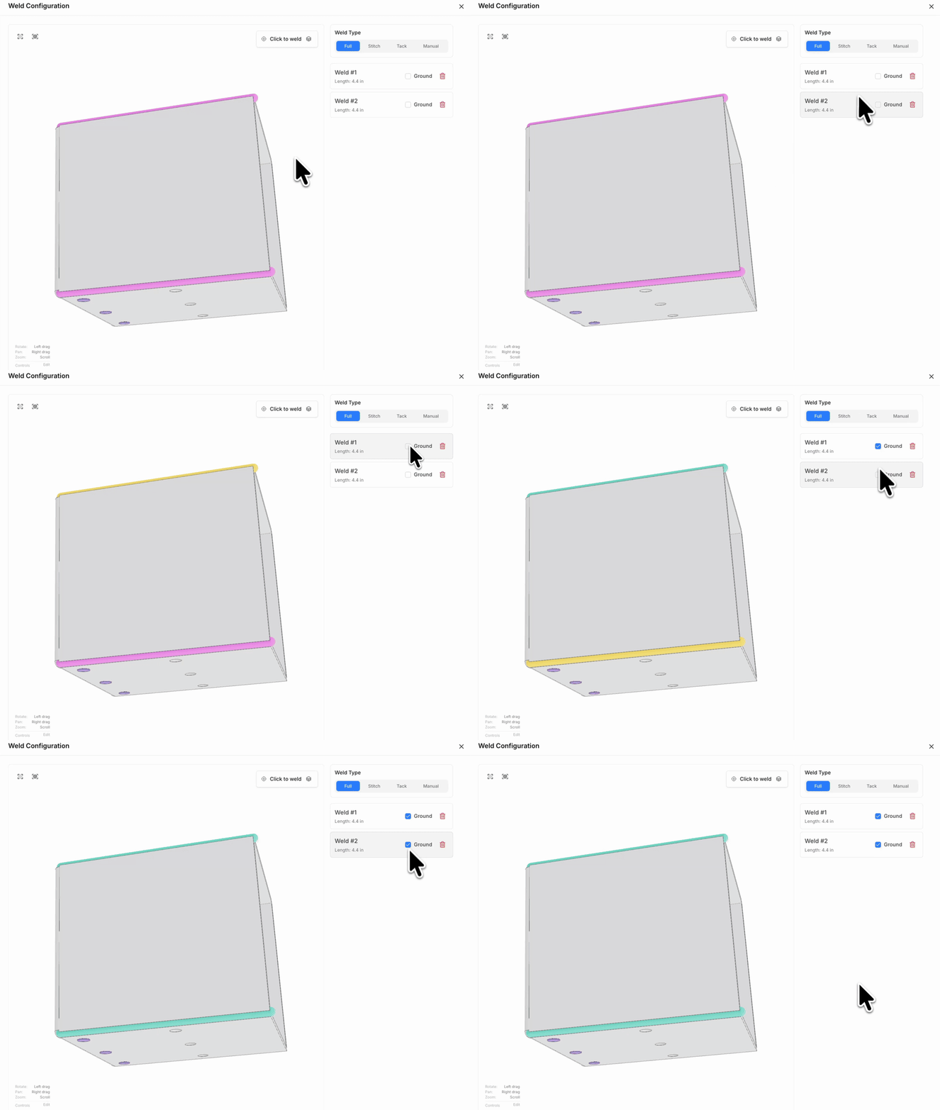
- Each bent part shows a Welding row. Click Open to open the weld configuration.
- Pick a weld type, then click a seam on the 3D preview to weld it. In Manual, hold and drag along a seam to place a segment.
- Toggle grinding on any weld from the list of welds. The price updates as you go.
The Welding row shows a count of the welds on the part. If the part isn't eligible, such as a galvanized steel part or one thicker than 0.250", the quote tells you why so you can change the material before checkout.
Welding design checklist
- The part is a single bent part and meets the bending guidelines.
- The material is aluminum, steel, or stainless steel, 0.250" or thinner, and not galvanized.
- Each welded corner uses the right setup for its thickness: full overlap, half overlap, or corner to corner.
- Every welded corner has a gap between the flanges within the range for its thickness.
- Seams that don't need to be sealed use stitch or tack welds to limit heat and distortion.
- Visible or powder coated corners are ground smooth.
For the full reference, see the welding guidelines. Not sure if your part can be welded? Upload your STEP file and open the Welding row on the quote.
Press Brake Simulation: Watch Your Part Bend Before You Order
Every bent part on a Fabworks quote now gets a press brake simulation. See each bend play out on our tooling, find collisions before you order, and learn what to change when no bend order works.
Use AI to Check Your Sheet Metal Parts for Manufacturability
Connect an AI agent to the Fabworks MCP server and have it check your STEP files for manufacturability, explain every issue, and re-check your fixes before you order.
Order Sheet Metal Parts
Upload a 2D DXF or 3D STEP file for an instant laser cutting quote. Quote in seconds, order in minutes, receive parts in days.
or drag and drop
STEP / DXF up to 24MB
Your files are safe, secure, and retain all intellectual rights.