Bump Bending: How to Form a Large Radius on a Press Brake
Tell Google we're a trusted resource.
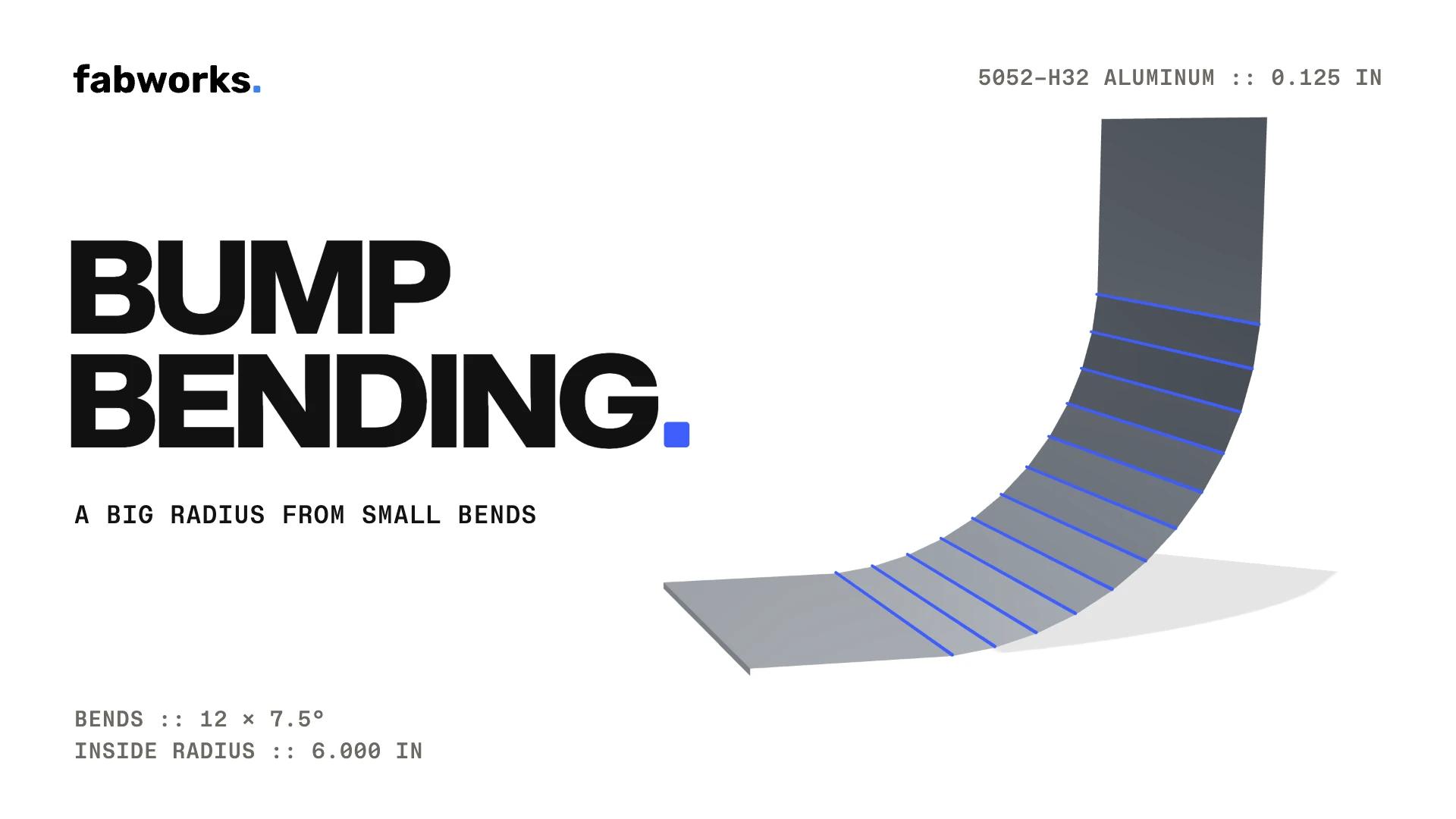
Bump bending, also called bump forming or step bending, makes a large radius in sheet metal without a special tool. Instead of one bend, the press brake makes a row of shallow bends along the sheet, each adding a few degrees, until the sheet has turned through the full angle. From a short distance the row of bends reads as a smooth curve.
A press brake bump bending a large radius, one small bend at a time.
To design a bump-bent radius:
- Choose the radius, the face it is measured on, and the total angle of the curve.
- Split the angle into equal bends, and space them evenly along the curve.
- Keep at least one die width between bends, so the sheet stays supported on the die.
- Model the curve in CAD as separate small bends, not one large-radius bend.
The calculator below works out the bend count, angle, and spacing for any material and thickness we bend.
Why Bump Bend a Large Radius
A press brake bend gets its radius from the tooling: in an air bend, the sheet wraps around the punch tip and spans the die opening. Our standard tooling forms a 90° bend with an inside radius of about half to three times the material thickness, depending on the material, and the bend radius calculator shows the exact radius for each material.
A radius of several inches would otherwise need a radius punch made for that one size, or a set of rolls. Bump bending uses the same punch and die as every other bend on the part. Our DFM check flags any bend modeled with an inside radius over 0.75" as Bend radius too large, so a larger radius has to be modeled as bump bends.
How Bump Bending Works
Each bump is a normal air bend, just a shallow one. The press makes a bend, the backgauge moves the sheet forward by the bend spacing, and the press makes the next. After the last bend the sheet has turned through the full curve.
The result is a row of short flats joined by small bends, not a true arc. It can't match a radius exactly, so the calculator keeps the part on one side of it:
- Inside radius: each flat touches the circle at its middle and each bend stands slightly outside it. Nothing cuts inside the radius, so use this when the curve wraps around something.
- Outside radius: each bend sits on the circle and each flat dips slightly inside it. Nothing stands outside the radius, so use this when the curve fits into something.
The largest distance between the part and the true arc is the gap:
- Angle per bend:
α = total angle / N
Fitting the inside radius:
- Spacing:
s = 2 × R × tan(α / 2) - Gap:
h = R × (1 / cos(α / 2) − 1)
Fitting the outside radius:
- Spacing:
s = 2 × R × sin(α / 2) - Gap:
h = R × (1 − cos(α / 2))
N is the number of bends and R is the radius on the face you are fitting, and the spacing is measured on that face. The formulas treat each bend as a sharp corner. The calculator also accounts for the small radius each bend really forms, which brings an inside-face bend slightly closer to the arc, and gives the flat-pattern spacing, which differs by a few thousandths of an inch.
How Many Bends, and How Far Apart
More bends give a smoother curve. Fewer bends cost less, because press brake time is priced per bend, so wide spacing keeps even a single part affordable.
The die sets the limit. Each bend needs the sheet resting on both die shoulders, so the flat between two bends can't be shorter than the minimum flange, about two-thirds of the die width on a shallow bend. That is all our DFM check requires, but the calculator keeps a full die width between bends so the sheet rests on flat material with room to spare. Thicker sheet bends on a wider die, so it needs wider spacing.
For example, a 90-degree curve with a 6" inside radius in 0.125" 5052-H32 aluminum, which we bend on a 16 mm die:
| Bends | Angle per bend | Spacing on the flat | Gap to the arc |
|---|---|---|---|
| 3 | 30° | 3.240" | 0.203" |
| 6 | 15° | 1.593" | 0.050" |
| 9 | 10° | 1.059" | 0.022" |
| 12 | 7.5° | 0.793" | 0.012" |
| 14 | 6.43° | 0.680" | 0.009" |
Twelve bends keep the part within our 0.015" bend length tolerance of a true arc, so that is where the calculator starts. Fourteen is the most that keeps a die width between bends at this radius, and the two extra bends smooth the curve by only 0.003". We can space bends tighter, but that takes test pieces and gives less consistent results.
Two more things to plan for:
- Angle errors add up. Each bend is held to ±1°, and a curve made of many shallow bends adds those errors together. If the curve has to match a mating part closely, order a test piece first.
- Keep holes on the legs. Holes and cutouts between the bends sit in each bend's distortion zone and can stretch. The straight legs are ordinary flanges, so they also have to meet the minimum flange length.
Bump Bending Calculator
The number of bends starts at the fewest that keep the part within 0.015" of the arc. Change it to see how the spacing and gap move.
Bump Bending Calculator
Work out how many bends, at what angle and spacing, form a large radius on our press brake tooling.
- Angle per bend
- 7.50°
- Bend spacing on the flat
- 0.793"
- Bend spacing on the inside face
- 0.787"
- Closest spacing we suggest
- 0.638"
- Curve length on the flat
- 9.520"
- Largest gap to the arc
- 0.012"
- Most bends we suggest
- 14
Modeling Bump Bends in CAD
Model the curve the way it is made: separate small bends with flats between them, not one large-radius bend. In most sheet metal tools, sketch the side profile as a polyline on the face you fit the radius to:
- Draw the first straight leg, ending at the first bend.
- Draw
N - 1lines, each as long as the calculator's bend spacing and each turned by the angle per bend. - Draw the second leg from the last bend, turned by one more angle per bend.
- Make a sheet metal flange or contour flange from the sketch, with the thickness added away from the center of the curve for an inside radius, or toward it for an outside radius.
- Use your CAD tool's default bend radius. Each corner in the sketch becomes one bend.
Export a STEP file and upload it. Each bump shows up in your quote as its own bend, checked for angle and minimum flange and shown in the press brake simulation.
Bump Bending FAQ
What is bump bending?
Bump bending, also called bump forming or step bending, makes a large radius on a press brake from a series of shallow bends spaced close together.
How far apart should bump bends be?
At least one die width. In 0.125" aluminum, which we bend on a 16 mm die, that is about 0.63".
How many bump bends do I need?
The fewest that make the curve smooth enough for the part. A 6" radius, 90-degree curve needs 12 bends to stay within 0.015" of a true arc.
What radius can a press brake bend without bump bending?
Only the radius its tooling forms, about half to three times the material thickness on our press brakes. For a larger radius, bump bend it.
For the rules that apply to every bend, see the bending guidelines and our sheet metal bending service. Upload your STEP file for instant pricing and a free DFM check on every bump.
Countersink vs Counterbore
A countersink is a cone for a flat head screw. A counterbore is a flat-bottomed pocket for a socket head cap screw. Here is how to pick between them for sheet metal parts.
Sheet Metal Fasteners: How to Choose the Right Hardware
How to choose sheet metal fasteners for a sheet or tube part. Covers PEM nuts, flush nuts, studs, standoffs, blind standoffs, and rivnuts, plus how material, thickness, and access narrow the choice.
Order Sheet Metal Parts
Upload a 2D DXF or 3D STEP file for an instant laser cutting quote. Quote in seconds, order in minutes, receive parts in days.