How to Auto-Add PEM Hardware to Your Parts
Tell Google we're a trusted resource.
If your part only needs one or two PEM nuts, picking them out by hand in the quoting configurator takes a few seconds. If it needs twenty, across a dozen holes, that stops being a good use of your time. Fabworks can now read the hardware straight out of your CAD model: model each nut, stud, or standoff as its own body, name it with the correct PEM part number, and export the whole assembly as one STEP file. When you upload it, we match every named body to its nearest hole and add the hardware automatically.
This post walks through how to set that up in your CAD software, what happens when we can't find an exact catalog match, and how to add hardware by hand in the quoting software for the parts where that's still easier.
Model Hardware Directly in Your CAD Software
Start from your normal sheet metal part, then add the hardware as its own solid body positioned exactly where it mounts, on the correct side of the sheet. Most CAD packages have a standard content or fastener library with real PEM geometry you can drop in and mate to the hole, which is the easiest way to get placement right.
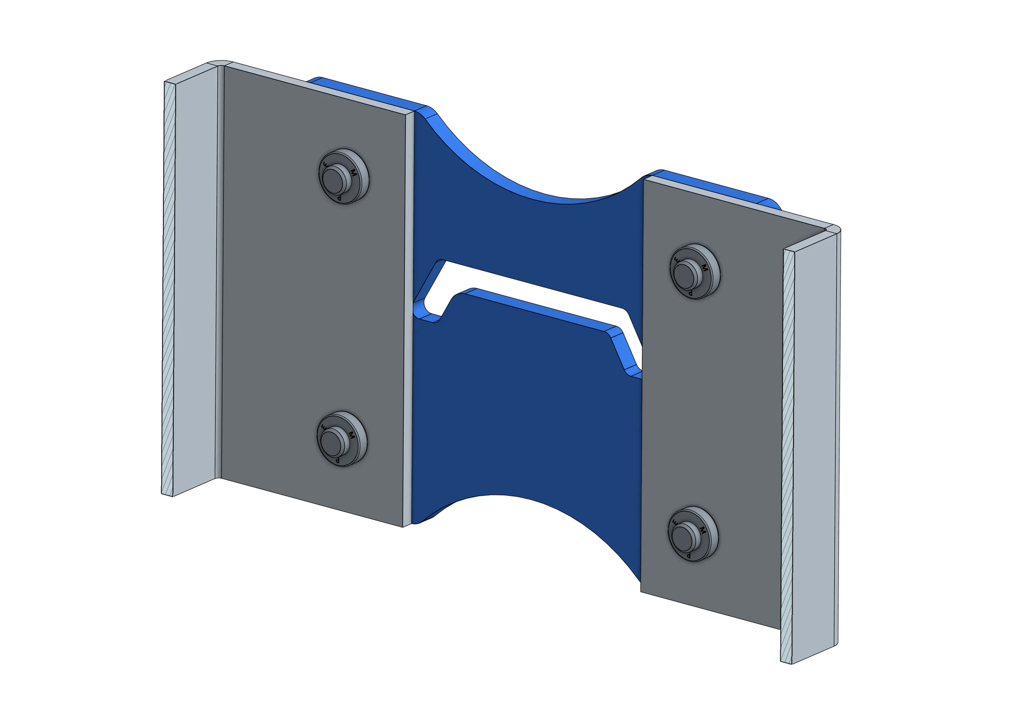
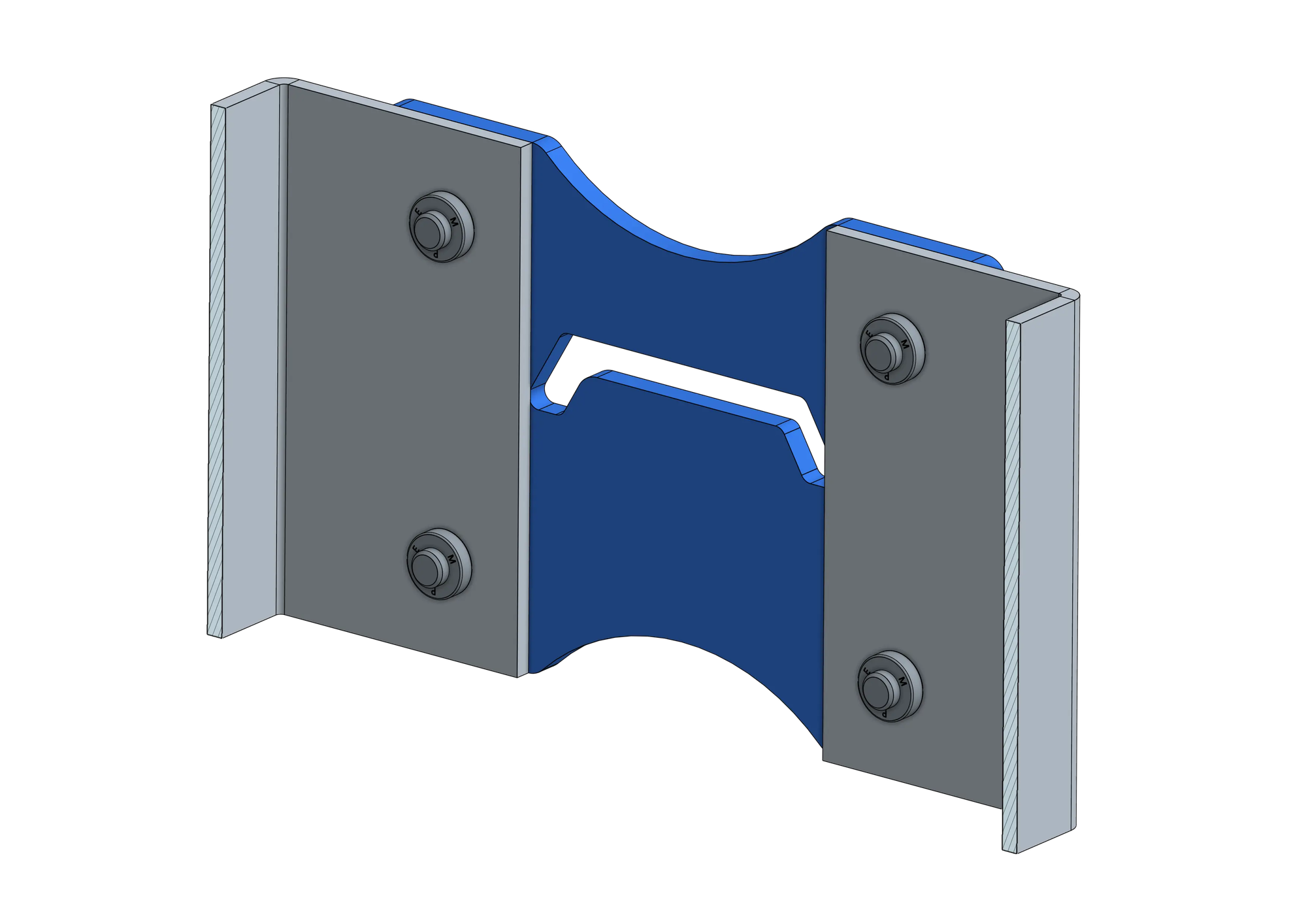
The bracket's sheet metal body next to its PEM nuts, modeled and positioned as their own bodies at each hole.
You don't need to model the sheet part and hardware as separate files or link them with an assembly structure your CAD tool has to preserve, we only need everything to end up as bodies in one exported STEP file. If you're not using Onshape, the same idea applies in Fusion 360, SolidWorks, or any other package that supports multi-body parts or assemblies. For general STEP export steps, see our guides for Onshape and Fusion 360.
Name Each Body With Its PEM Part Number
This is the step that makes auto-detection work: rename each hardware body to match its PEM part number from our hardware catalog. We match on the part number pattern inside the name, so a body named PEM S-M3-0ZI and one named just S-M3-0ZI both work, and it's not case-sensitive.
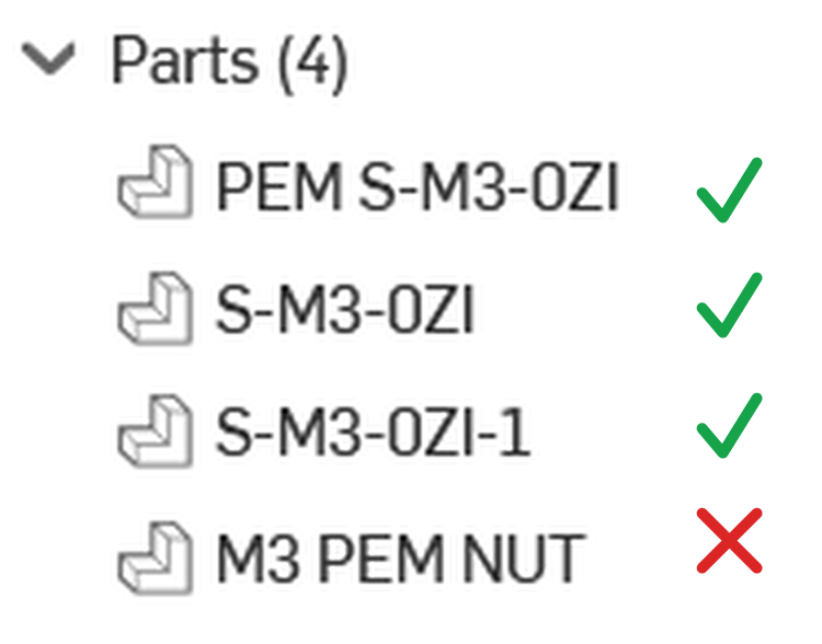
The first three all resolve to the same part. The "PEM " prefix is optional, so S-M3-0ZI on its own works fine. S-M3-0ZI-1 works too, that trailing -1 is what CAD software often appends automatically to keep multiple instances of the same part uniquely named, and we only read the part number, not whatever's tacked on after it. M3 PEM NUT fails: it's a description, not a part number, so we can't extract a SKU from it at all, and that body won't be recognized as hardware.
The part number itself has to be exact: series, thread size, and length code, separated by dashes, matching a real entry in our hardware catalog. A few examples across hardware types: S-M3-0ZI (nut), F-M4-0ZI (flush nut), FH-M6-12ZI (stud), SO-M4-6 (standoff), BSO-M5-10ZI (blind standoff). Use the part number for the exact hardware you modeled, not a rough equivalent, the more precise the name, the better the match on the other end.
Export as a Multi-Body STEP File
Once every piece of hardware is modeled and named, export the sheet part and all of its hardware bodies together as a single STEP file, the same multi-body export used for uploading assemblies. Don't export each body separately.
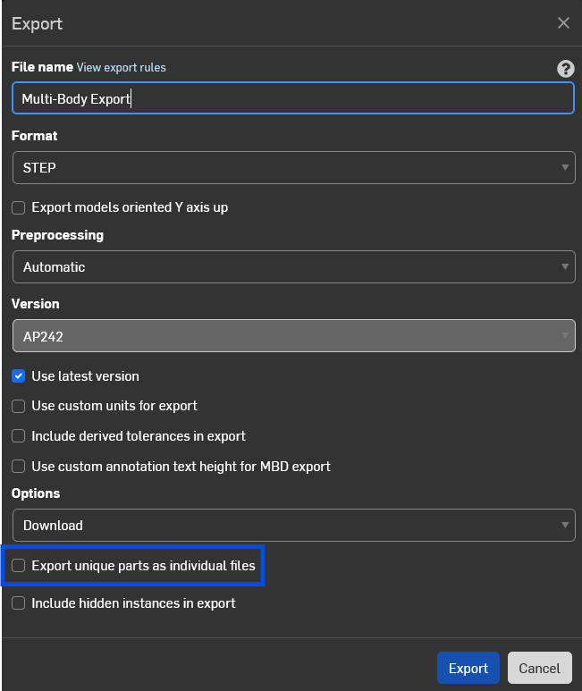
In Onshape, leave "Export unique parts as individual files" unchecked so the sheet part and its hardware bodies all export together into one STEP file.
Upload It and Let Fabworks Match It
Drop the STEP file into an instant quote like any other part. During processing, we look at every named hardware body, find the closest hole on the sheet part within about 3/4", and figure out which side of the part it mounts on. If the part number is an exact match for hardware we stock, it's added to that hole automatically, no extra clicks needed.
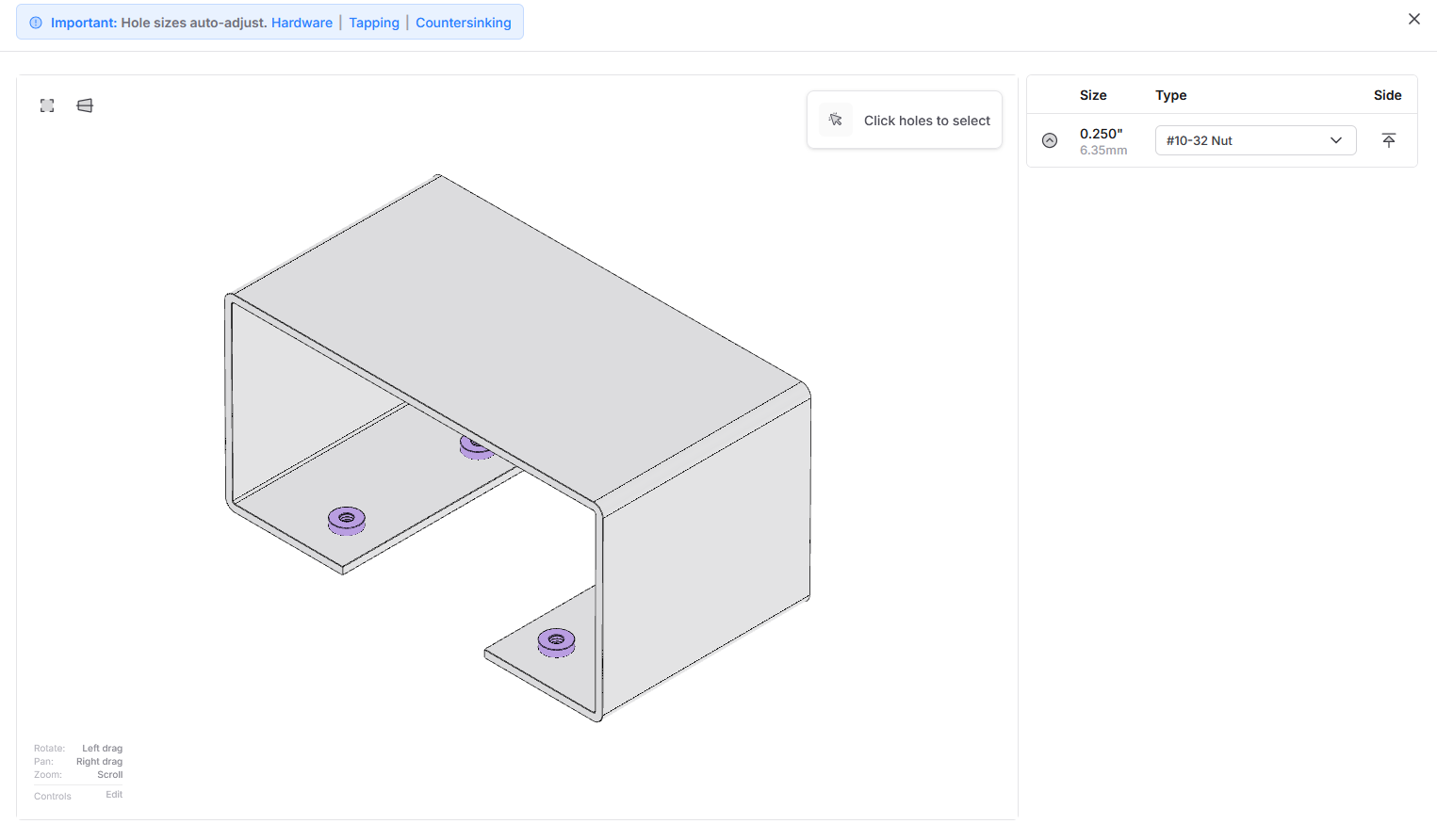
All three holes on this part already show #10-32 Nut in the Type column, matched and applied automatically from the named hardware bodies in the STEP file, before anyone touched the Hole Ops panel by hand.
When There's No Exact Match
If the part number you modeled isn't in our stocked catalog, exactly, we don't just drop it. We look for the closest equivalent, same hardware type and thread size, and flag it with an "Unrecognized PEM hardware" notice so you can review it before your quote is finalized.

Here, SOS-032-8 isn't a stocked part number, so we suggest the closest supported option, SO-032-10ZI. Click Configure to accept the replacement, or the X to dismiss it and set that hole up yourself.
Adding Hardware Manually in the Quoting Software
You don't have to model hardware in CAD to use it. If it's just a hole or two, or you're working from a design that didn't include hardware bodies, you can still add PEM hardware directly in the quoting software: click a hole, filter by hardware type, Nut, Flush Nut, Stud, Standoff, or Rivnut, and pick the exact size from the list.
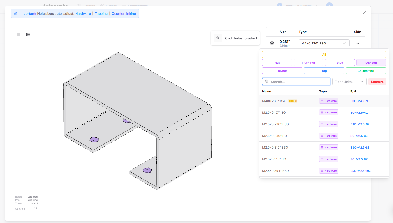
Click a hole, filter by hardware type, and search or scroll to the exact size you need. If a size you've used elsewhere on the part is close but not exact, it's flagged "closest" in the list.
This also works alongside the auto-add feature. Anything we detect from your STEP file shows up already configured; anything you'd rather add or change by hand, you still can.
Bringing It Together
Modeling and naming your hardware correctly turns a repetitive manual step into something that happens automatically when you upload. It's most worth doing on parts with several pieces of hardware; for a single hole, adding it by hand in the quoting software is just as fast.
Having trouble picking out which hardware you need in the first place? Watch our guide on how to pick out hardware for your parts.
Our guide to designing with PEM hardware and PEM hardware guidelines also cover how to choose the right nut, stud, or standoff for your material and thickness.
Wave Bends: Fold Sheet Metal by Hand
A free Onshape FeatureScript that cuts wave bend slots along a bend line, so the tabs left between them are weak enough to fold by hand. How to install it, how to size the slots, and when a wave bend is the right call.
How to Choose the Right Material for Your Parts
A practical framework for picking sheet metal material, thickness, and finish, weighing cost, weight, and corrosion resistance, plus when to powder coat versus order galvanized steel.
Order Sheet Metal Parts
Upload a 2D DXF or 3D STEP file for an instant laser cutting quote. Quote in seconds, order in minutes, receive parts in days.
or drag and drop
STEP / DXF up to 24MB
Your files are safe, secure, and retain all intellectual rights.