Essential Checks Before Ordering Sheet Metal Parts
Before submitting your order for laser cut and bent sheet metal parts, it's crucial to review your design for common issues that could affect manufacturability or part quality. This guide will help you catch and correct potential problems, ensuring smoother production and better results.
Check Flange Lengths
One of the most frequent issues in sheet metal design is insufficient flange length. Short flanges can lead to difficulties in bending and reduced structural integrity.
- Check all flanges against the minimum length requirements for your chosen material and thickness. Refer to Fabworks' bending guidelines for specific measurements.
- Pay extra attention to small tabs or narrow sections that may be challenging to bend properly.
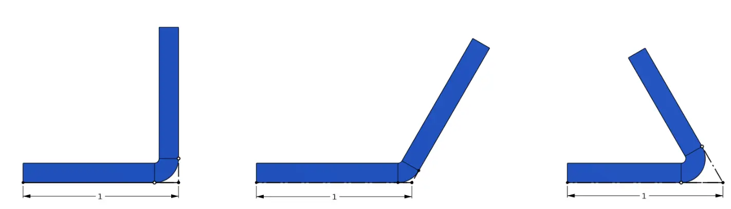
Here is a diagram of how to properly measure the length of a flange. Notice how a sharper bend will reduce the usable flat area on the flange.
Feature Proximity to Bends
Features placed too close to bend lines can become distorted during the bending process, affecting both aesthetics and functionality.
- Review the placement of holes, slots, and other features near bend lines.
- Ensure all critical features fall outside the distortion zone for your material thickness. Consult Fabworks' bending guidelines for precise distortion zone measurements.
- If a feature must be close to a bend, consider adding relief cuts or adjusting the design to accommodate potential distortion.
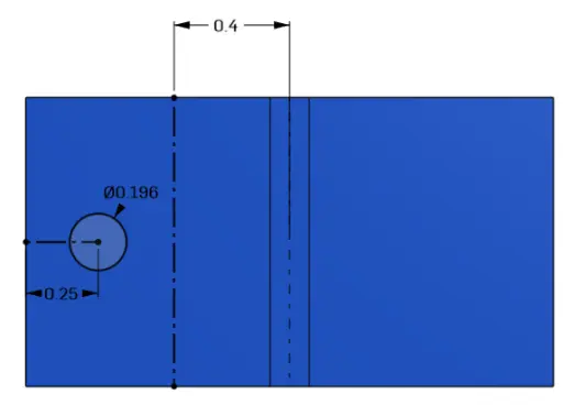
This part is made from 0.125" Thick 5052-H32 Aluminum which calls out for a distortion zone of 0.4". This distortion is measured from the bend line in the direction of the feature. In this case you can see that the hole is outside of this 0.4" zone meaning it will not be deformed by the bend. Non critical features can enter this zone slightly, just be aware that they will be deformed by the bending process relative to how close they are to the bend.
Tolerance Considerations
Accumulated tolerances across multiple bends can lead to significant deviations in final part dimensions.
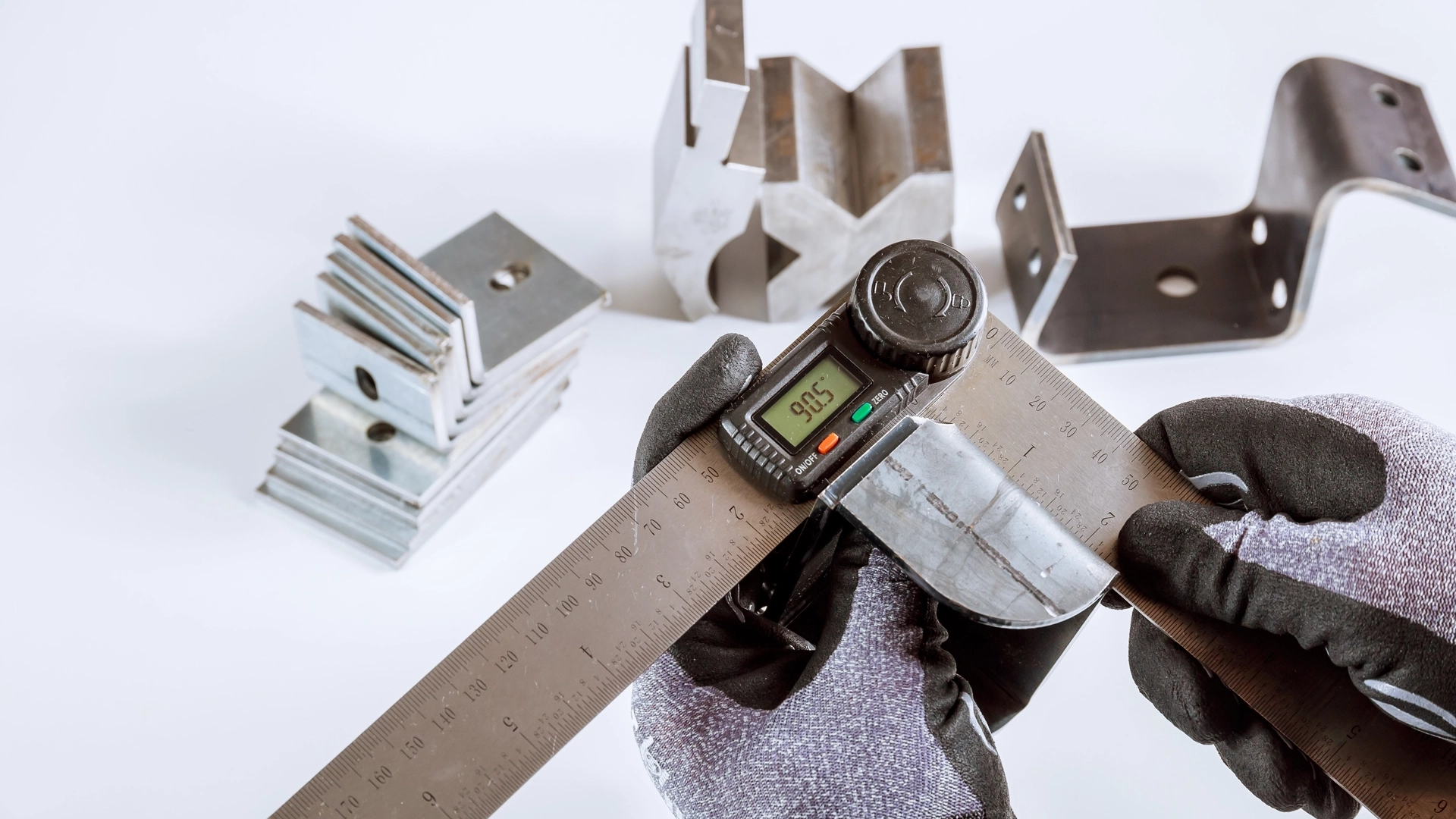
- Be aware that each bend introduces some dimensional variability. Fabworks maintains tight tolerances (+/- 0.015" for length and +/- 1 degree for angles) per bend, but these can add up in complex parts.
- For parts with multiple bends, consider designing with slightly looser tolerances where possible to accommodate potential variations.
- If precise alignment is critical, consider incorporating adjustment features or slots instead of relying solely on bend accuracy.
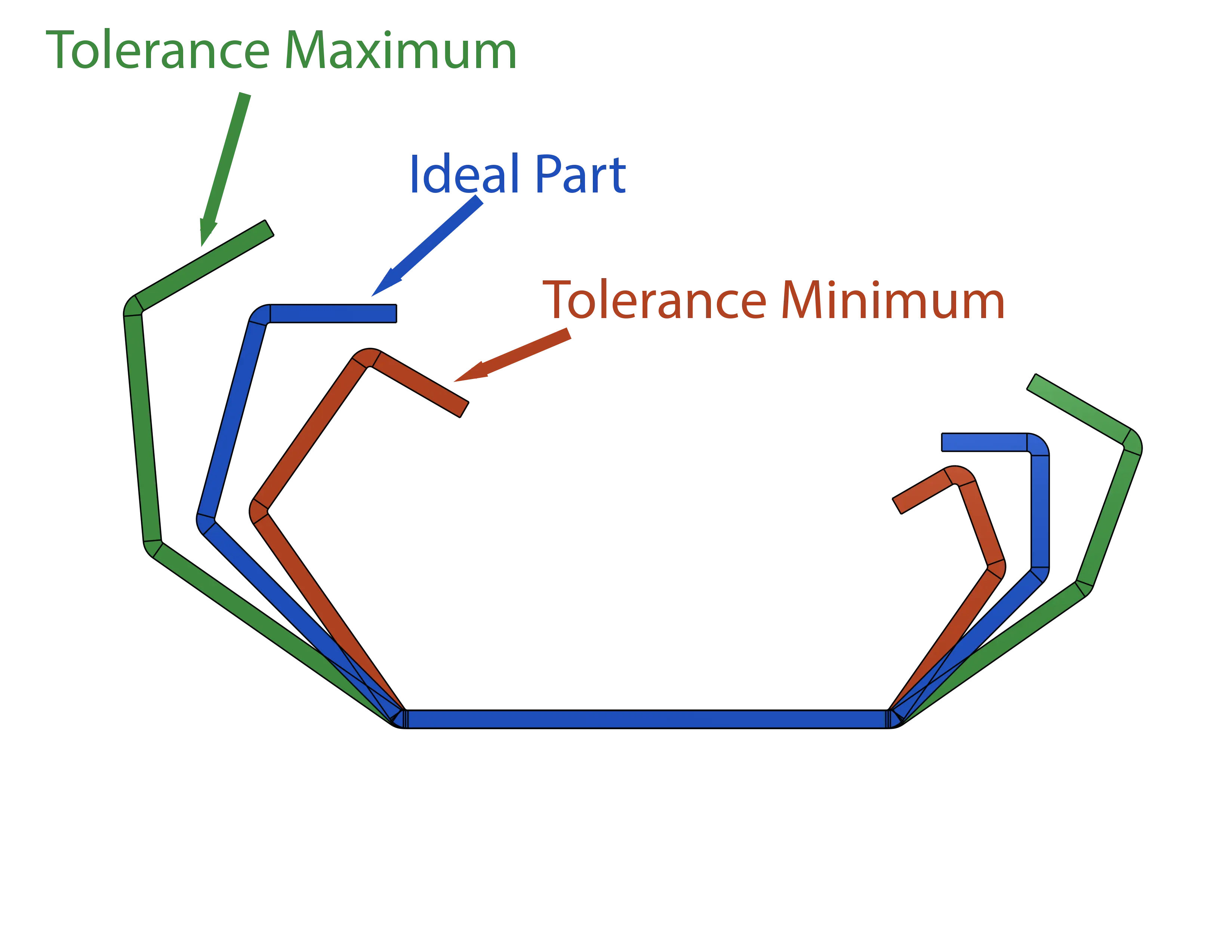
Below is a representation of how tolerance stackup can change the shape of a part. The tolerance has been scaled up to 10x its actual value for visualization purposes. The main thing to notice is how after each subsequent bent the part gets further and further from its expected shape. Sheet metal, particularly thinner gauges and larger parts, possess a degree of elastic deformability. This property can sometimes be advantageous in achieving proper fitment, especially when dealing with minor dimensional discrepancies. However, it's important to note that relying on this flexibility should not be used in precision parts, and flexibility should be modeled into the part.
Correctly Modeled Bend Radius
Using the wrong bend radius in your CAD model can result in unexpected part dimensions after bending.
- Ensure all bends in your model use Fabworks' standard bend radii.
- Double-check that this radius is consistent across all bends in your part.
- Remember the actual produced part may have slight variations due to material properties and tooling.
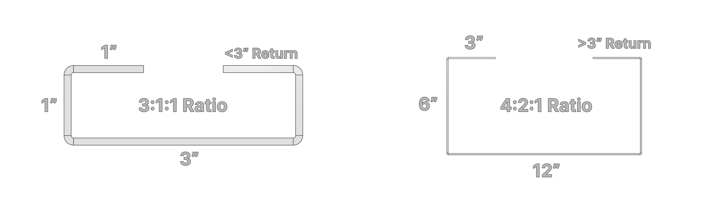
Reverse Bend Ratio
Reverse bends (two bends in opposite directions close together) require careful consideration to avoid material failure or tooling issues.
- Review any areas with closely spaced opposing bends.
- Ensure these sections meet Fabworks' minimum ratio guidelines:
- For small reverse bends (< 3" long): Maintain a 3:1:1 ratio
- For larger reverse bends (> 3" long): Maintain a 4:2:1 ratio
- If your design doesn't meet these ratios, consider adjusting the part geometry or splitting it into separate components. For methods of joining those two pieces back together check out our blog post on joining techniques.
Material Thickness
Incorrect material thickness in your model can lead to unexpected results, especially in bent areas. For a list of all available materials, thicknesses, and thickness tolerances refer to the materials section of the Fabworks Resources
- Verify that your CAD model uses the exact thickness of the material you're ordering.
- Pay special attention if you've modified a pre-existing design, as it's easy to overlook thickness changes.
- Remember that nominal thicknesses (e.g., 1/16") may not match exact decimal values (0.0625"). Use precise measurements in your model.
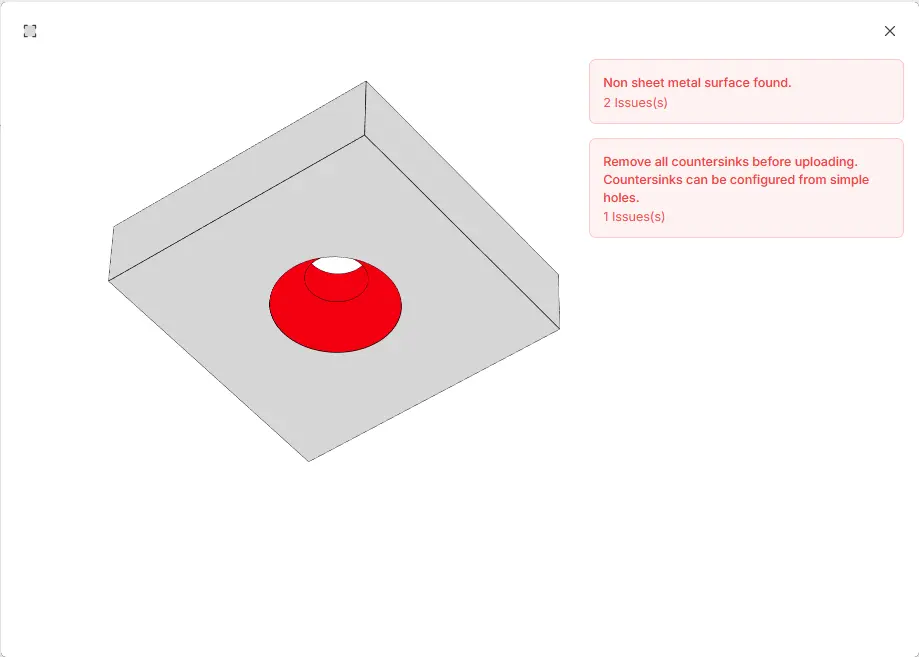
Avoid Modeling Certain Features
Some features should not be modeled in your CAD file, as they're better specified during the quoting process. Modeling these features can lead to errors with the file upload.
- Do not model countersinks, or threads in your STEP file.
- Instead, export a clean model and specify these features when configuring your quote in Fabworks.
- This approach ensures proper sizing and application of these features during manufacturing.
Additionally if you plan on counterboring, or adding other partial-depth features to your parts after receiving your order, do not include them in the model you send in, as it will error out in the file upload.
Final Thoughts
By carefully reviewing your designs with these points in mind, you can significantly reduce the likelihood of manufacturing issues and ensure your parts meet your expectations. If you're unsure about any aspect of your design, don't hesitate to reach out to Fabworks' support team. They can provide guidance and help you optimize your parts for successful production.
Remember, a little extra time spent on design review can save considerable time and resources in the long run, resulting in higher quality parts and more efficient production.
Joining Techniques for Laser Cut Parts
Explore essential sheet metal joining techniques, from welding to adhesive bonding, to create durable and efficient parts for any project.
How to Prevent Rust on Laser Cut Parts
Discover effective strategies to prevent rust on laser cut metal parts, from material selection and protective coatings to design tips and post-production care.
Order Sheet Metal Parts
Upload your STEP file for an instant laser cutting quote. Quote in seconds, order in minutes, receive parts in days.
or drag and drop
.STEP / .STP up to 25MB
Your file are safe, secure and retain all intellectual rights.